TRUSS STYLES OF COVERED BRIDGES
Plank-Lattice (Town Lattice) Truss:
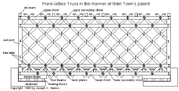 The Plank-lattice Truss (often referred to as the Town Lattice Truss)
The plank-lattice design was first patented in 1820 by architect Ithiel Town of New Haven, Connecticut. Mr. Town promoted the use of his invention, sending agents all over New England. If a builder chose to use the design, Town’s agent would license him for a one-dollar royalty per foot of bridge. If a builder was found using the design without permission, the royalty fee was doubled. Town made his fortune not by building bridges, but by selling the rights to use his design.
The timber bridges were fastened together with mortise and tenon, tediously drilled, chiseled, and–finally–pegged. The lattice bridge is constructed entirely of planks instead of the heavy timbers used in the Queenpost and Kingpost trusses. The planks, usually of spruce or hemlock, are simply fastened with hardwood pegs called treenails (pronounced trunnels). A lot of treenails are needed however–it was noted by a bridge carpenter that over 2,500 holes must be drilled to receive nearly a thousand treenails to assemble a 100-foot lattice highway bridge.
The treenails are used to pin the chord planks together on both sides of the lattice and to pin the lattice planks together where they cross. The chords usually consist of four layers of planks– two layers on each side of the lattice. A strong chord requires that the planks should not be less than thirty feet long and that the plank pairs should overlap one another by half their lengths. The chord-plank pairs are pinned together at a lattice-plank crossing with three or four treenails. The lattice-plank crossings are secured with two treenails except where the chords cross.
The plank-lattice design calls for four chords on each truss–the lower chord and secondary lower chord and the upper chord and secondary upper chord. The bridges built with the four pairs of chords have held up well over the years against wind, water, and heavy loads. Only three of Vermont’s plank-lattice bridges built without upper secondary chords survive–the School House Bridge in North Troy, the Scott Bridge in Townshend, and the Worrall Bridge in Rockingham. All three have required additional bracing.
“The main thing about the plank lattice was, it was the cheapest and easiest to build,” says Paul Ide, framer and joiner of bridges and barns. “Any carpenter would be able to build it quickly, without large dimension timber. You didn’t need anything thicker than three inches for your chords, and generally, you didn’t need a plank longer than thirty-two feet.”
The usual angle in the lattices constructed in Vermont is 45 degrees, with some as steep as 55 degrees. The average length of Vermont’s surviving lattice truss bridges is 105 feet. Plank sizes are typically three by eleven inches with the lattice spaced at three-foot intervals.
From Spanning Time Vermont’s Covered Bridges, by Joseph C. Nelson
Kingpost Truss:
 The Kingpost truss, in its simplest form, is found in frame buildings where there is a need to provide large spaces without columns or load bearing walls. The most common form found today supports the roofs of small commercial buildings and the ubiquitous post-World War II ranch- style homes those rambling houses with the low-pitched roofs and no useful attic space. These mass-produced roof trusses, found in any lumber yard, are descended from the structures used in the huge old barns and meeting houses that had cavernous interiors, constructed with post and beam and fastened with mortise and tenon.
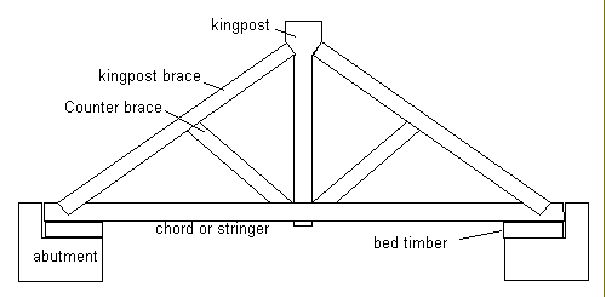
The Kingpost truss was adapted to support the shorter bridge spans. It was probably first used with small open-work bridges, and it represented quite an improvement over stringer bridges, in which the trunks of trees were simply thrown over a stream.
In the Kingpost truss, a timber called the Kingpost, is in effect, suspended by its top end by two diagonal timbers whose ends are braced on the ends of the chord above the abutments on each stream bank. The center of the chord is suspended from the Kingpost. The weight of the bridge is transmitted to the ends of the chord through the Kingpost braces. The Kingpost braces are said to be in compression, squeezed between the chord-ends and the Kingpost by the weight carried by the Kingpost. The Kingpost, being stretched by the weight of the roadway and the outward thrust of the Kingpost braces, is said to be in tension. The chord is in tension as well, supported at the abutments and by the Kingpost and stretched by its own weight and the weight of the roadway. As long as the truss, its joints, and its timber members are strong enough to bear the stresses of compression and tension, the bridge will stand.
The carrying capability of the Kingpost truss requires that the angles between the Kingpost braces and the chords not get too small, meaning that a wider stream would require a really tall Kingpost. The maximum practical span for a Kingpost bridge is a little over forty feet. Longer spans require a more sophisticated truss. The Queenpost truss, for example.
From Spanning Time Vermont’s Covered Bridges, by Joseph C. Nelson
Howe Truss:
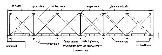 William Howe patented a wood and iron rod truss in 1840 and extended the patent with improvements in 1850. The truss was the first to be designed using mathematical stress analysis. The Howe truss, suitable for heavy duty bridge spans, was adopted by the railroad industry and became one of the most widely used trusses for railroad bridges.
The truss consists of wooden upper and lower chords, the chords linked together with sets of dual iron rods and wooden braces and counter braces. The braces and counter braces are butted against the chords on angle blocks. The rods are adjusted with nuts.
Of the four Howe truss bridges in Vermont, three are highway bridges. The Gold Brook Bridge in Stowe, built in 1844, is the oldest and is a miniature of the other three. The retired Rutland Rail Road Bridge in Shoreham is the last of Vermont’s Howe truss railroad spans. The Connecticut River bridges in Lunenburg and Lemington, both Howe Truss highway bridges, are constructed with identical components, both having been built by the same company. The iron rods are one-and-three-quarter-inches in diameter, the braces measure seven by nine inches, and the counterbraces are six by six inches. The angle blocks are wood.
William Howe, born in 1803 in Spenser Massachusetts, came from a family of inventors. Tyler Howe invented a spring bed and Elias Howe was the inventor of the sewing machine.
For more on the Howe Truss and William Howe see Yankee Science in the Making, by Dirk J. Struik
From Spanning Time Vermont’s Covered Bridges, by Joseph C. Nelson
Haupt Truss:
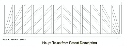 The Sayers Bridge in Thetford, Vermont is said to be the only example of the Haupt truss in New England. Curiously, the Sayers’ truss lacks the defining lattice structure of the braces shown in Haupt’s patent drawings. Instead of the lattice-like assembly of braces, it has a long and high timber arch similar in construction to Burr’s arch. See below.
Note that the brace configuration in Haupt’s truss implementation distributes, at least for the first several truss panels, compression forces more directly to the abutments than does the Sayers Bridge truss. This is a key feature of the Haupt patent. The Sayers’ truss, rather, performs like a “multiple Kingpost truss with auxiliary arch.” The differences between the two truss implementations, then, are more than trivial.
Herman Haupt was born in Philadelphia, Pennsylvania in 1817. He died in 1905 in Jersey City, New Jersey. He graduated from West Point in 1835. He resigned his commission to become district superintendent and chief engineer for the Pennsylvania Railroad. In 1839, he designed and patented the Haupt bridge truss. When the Civil War began, he was drafted to serve as superintendent of military railroads. He rose to the rank of Major General. Civil engineers may remember him for his text books on bridge construction and his work on the five-mile railroad tunnel through the Hoosic mountain range in northwest Massachusetts.
From Spanning Time Vermont’s Covered Bridges, by Joseph C. Nelson
Burr Truss:
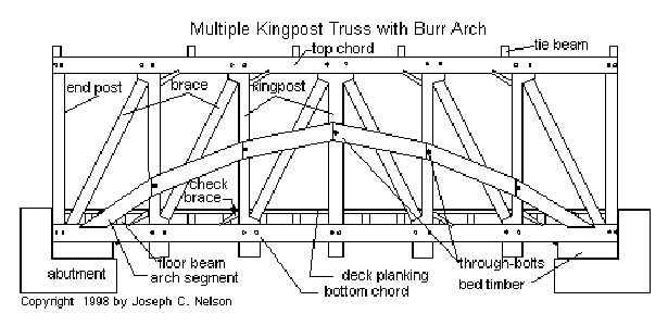 Theodore Burr built a bridge across the Hudson River in Waterford, New York in 1804. There, he used a combination truss and segmented arch that became the basis of his 1817 patent. The patented truss consisted of parallel chords tied together by vertical posts and stiffened by crossed braces. Each timber-arch segment, lap-jointed on both ends, is fitted into the next on both sides of the posts and braces. The segments are “through-bolted” to the vertical posts, sandwiching the truss. The ends of the arches are received by the abutments below the bed timbers.
The Vermont versions, except for the bridge serving the Shelburne Museum, differ from Burr’s patent in that the ends of the arch are supported by the ends of the lower chords rather that at the faces of the abutments. Also, a multiple-Kingpost truss is used rather than the cross-braced truss.
The Burr truss is not a true arch-bridge in that the parallel-chord truss system and the arch act in concert to support the bridge and its load. The multiple-Kingpost truss serves the purpose of aligning the arch segments while carrying the road-bed. The arch serves to make the whole structure more rigid, and the combination is capable of longer spans than is the multiple-Kingpost truss alone. The Burr-type bridge is best classed as an auxiliary arch system. In a true arch bridge, the roadway is supported only by the arch.
How the Burr truss actually works is “a thorny topic of debate,” according to Gilbert Newbury, an engineer with the Vermont Agency of Transportation. Newbury, who is trained in timber engineering, planned the repair of the Burr-arch bridge on Gates Farm in Cambridge. He explains that one school of thought has it that the arches do the work, the other believes it is the parallel chord truss.
Newbury’s computer analysis and field observation indicate that it is the truss that carries the majority of the bridge and roadbed weight, with the plank arch acting as a stiffening element for the truss.
From Spanning Time Vermont’s Covered Bridges, by Joseph C. Nelson
Actual blueprint for a 1920’s 60-ft Howe Truss
Printable Covered Bridge Plans
Most truss information source is from: Spanning Time; Vermont’s Covered Bridges, by Joseph C. Nelson Available on Amazon